Integrating IMU angular rates with quaternions
This post is a copy of an old post from my previous website (that went down a few months ago); it was originally written in 2017.
Applications of orientation tracking, and associated challenges
Orientation tracking is present in many tasks and objects of daily life. Smartphones and apps rely on orientation information, virtual reality headsets need to keep track of the orientation of the head of the user to generate visual information, UAVs rely on IMUs and Kalman filters (or equivalent) to keep track of position, attitude etc. More generally the availability of cheap MEMS sensors that can measure linear acceleration, angular rate, and magnetic vector make it possible to keep track of orientation and are being included in an always growing number of objects.
However, using the data generated by such sensors to produce information about orientation requires a bit of processing. Considering the simplest problem of ‘naive’ orientation tracking based on the angular rate measured by a gyroscope, one needs to integrate the gyro information. One note at this point: traditionally speaking, gyroscopes were devices based on a fast rotating wheel that kept constant orientation in space (thanks to conservation of momentum), while the ‘gyros’ we speak about when using MEMS are measuring rather angular rate, i.e. the motion in rad/s that the MEMS is experiencing along each axis. In all the following, I will refer to those MEMS as gyros, even if this is maybe not the best word.
Performing the integration of the gyro signal requires a bit of mathematics, as keeping track of rotations in 3D can be tricky without the right tool. In addition, such naive implementation has several shortcomings - the main one being, as gyros are not perfect, the integrated orientation will tend to drift with time; this last point is usually adressed using some sort of Kalam filter.
In this post, I only talk about solving the ‘naive’ orientation tracking problem, i.e. integration of gyroscope data (angular rates in the case of MEMS). I do not speak about the harder case of combining measurements from several sensors as a Kalman filter would do.
Mathematical methods for orientation tracking
Describing rotations in 3D can be a bit tricky. One of the reasons for this is, rotations in 3D do not commute. As a consequence, there is no really obvious, canonical way to describe any arbitrary rotation in 3D with matrices. Of course, rotations around each axis of a cartesian coordinates system are easy to write, but the successions of several such rotations becomes quite complicated with matrix formalism, and it is easy to make mistakes using this description and difficult to quickly identify what rotation is defined by simply looking at its matrix. In addition, using elementary rotations such as done with for example the Euler angles description can lead to gimbal lock, which means that in some situations this description fails.
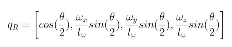
Happily, there is one good formalism for description of rotations in 3D, which is the one of quaternions. A quaternion is a collection of 4 real numbers, which together form an extension of complex numbers. Unit quaternions, which are quaternions of norm 1, have therefore 3 degrees of freedom, which is enough to describe any rotation in 3D. While quaternions can look a bit strange at the first look, considering quaternions from a purely ‘utilitarian’ point of view with the aim of describing rotations in 3D is really simple and can be summarised by just a few equations. If you want to use quaternions, you should have a look at this 2-pages summary (as a pdf). To summarize even further (but you should look at the pdf to see what the notations refer to), unit quaternions are a description of rotations:
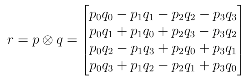
In addition, a product between quaternions is defined as:
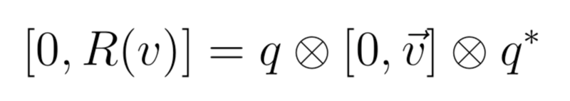
Which makes it easy to compute rotations in 3D:
More details are available in the pdf. The main point is that, with quaternions, one can forget about all difficulties such as gimbal lock, ordering of the euler rotations etc and instead just apply a few mathematical formula, with no thinking required.
An example implementation of orientation tracking using quaternions
A simple code performing integration of gyro data using quaternions is available on my Github. The implementation supposes that an Arduino reads data from an Adafruit LSM9DS0 board, but any other board giving access to a gyro would work as well. You can see that the code works well, even if there is some drift taking place with time as no method such as Kalman filtering is used to compensate for gyro drift.
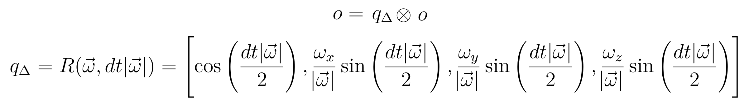
While many modules are available in all programming languages for performing computations on quaternions, I implemented the necessary functions again in Python. Of course, Python is not the best language when it comes to execution speed, but it is enough for a simple demonstration of gyro integration using quaternions. The gyro on the LSM9DS0 board is sampled at 50 Hz and the results transmitted to the computer. The Python code on the computer works in the following way. A quaternion, noted o for ‘orientation’ in the code (file ComputerSide/QuaternionAngularRateIntegration.py in the Github repo), is used to describe the rotation that transforms from the IMU to the fixed Earth referential. Therefore, each time the gyro gives a new output vector &omega , the quaternion o is updated as:
Going further: real world applications
As you can see this approach is working nicely, and it hopefully has some pedagogical value, but there are actually several limitations to what was presented here. First, using Python for doing some ‘real time’ computations is not the best option, as Python is interpreted and therefore quite slow. The reason I chose Python for the computer side code is that it is much quicker to develop some working code with Python than for example C++, and once you get a code that is working without bug it is quite easy to translate it into, for example, C++. So by rewriting into C++, I could get much faster looping and therefore smaller dt, leading to better reactivity and less error in the integration.
The other point to be aware about is that such an approach based on integrating the signal from a gyro will tend to drift with time, and that we are doing nothing here to compensate for this. In a real world application, one would combine (through, for example, a Kalman filter) the output of the gyro with the one from other sensors to avoid such drift. If I have time I will write on Kalman filters later on.
Simple, keep it stupid simple, quaternion and 3D computations library
I have been working on a small C-style library implementing the basis of quaternion, 3D vectors, and rotations. It is available here on github and should be usable with Arduino or any other C or C++ codebase, by just copying a couple of files.